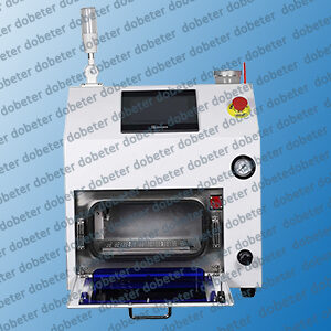
Solder Paste Inspection
- 1、Design concept
- 2、Product Application
- 3、Product Feature
- 4、Function Introduction
- 5、Basic Principe
- 6、Calibration
- 7、Operation Interface
- 8、Data Specification
- 9、Q&A
- 10、Application Case
1、Design concept
2D SPI—Solder paste thickness gauge -mainly for the solder paste printing process, it is necessary to truly master the smoothness of the solder paste printing thickness, so as to achieve the design concept product derived from the SMT process standard thickness. Ideal inspection for solder paste thickness, dealing with the increasingly growth of fine pitch, enhanced printing technology and high precision requirement.

2、Product application
•Solder paste thickness benign measurement.
• Determination of solder paste scraper pressure level.
• Measure area ,volume, line length and angle on PCB.
• Manifold Measure value for Statistical charts
• process capability index be provided as the real-time data for quality control.
• Measure printed solder thickness, height, length and interval.
3、Product features
• windows operating interface , exchange Chinese and English.
• Automatic measuring thickness of solder paste.
• Measure printed solder width, length and interval manually .
• Create area ,volume and sectional area automatically.
• Save and print measure result.
• Create statistics chart and X-BAR ,Range chart.
• Caculate CP and CPK automatically.
• Save the datasheet depends on the different SMT product line.
• Single and Multilateral measure datasheet.
• Manual adjust camera focus according to the PCB thickness.
4、Function introduction
• Measure printed solder thickness, height, length and interval.
• Providing various of the distributive thickness chart.
• Analyze thickness for solder cross-section.
• Create area and volume automatically.
• Providing various kind of statistical charts, such as the distributive thickness chart, X and R control chart , process capability index: Cp, Cpm ,Cpk for reference.
5、Measuring principle -1
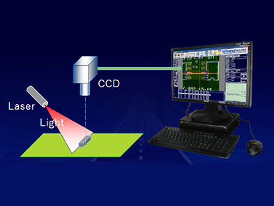
The laser beam is used to project from the side at 45 degrees. The higher object (solder paste or micro device) is first projected to the laser, and then projected to the lower substrate plane. In this way. According to the trigonometric function relationship,so as to achieve non-contact rapid measurement.
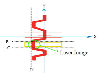
5、Measuring principle -2
Imaging generated by laser beam projecting onto the solder paste printing base.
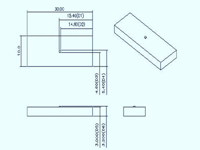
6、Datum correction
1. Standard calibration module by 0.5mm measurement.
2. First to calibrate the laser line and work-table before calibration.
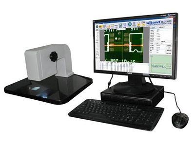
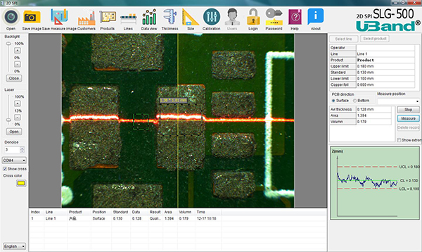
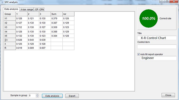
7、Operation interface — main screen
7、Operation interface — Pass rate
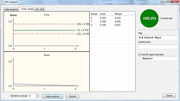
7、 Operation interface — X-R
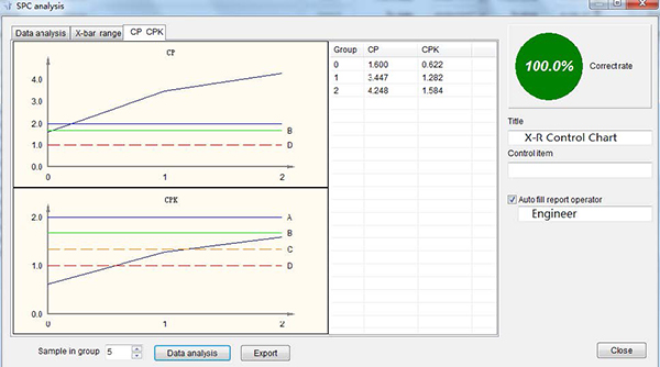
7、Operation interface — CP -CPK
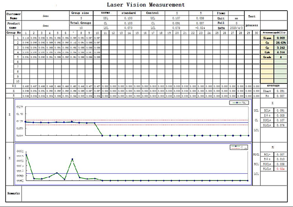
7、Operation interface — SPC List
8、Technical indicator
| Vision Range | 10.5 mm x mm x 7.5 mm |
| Camber | ≤2mm |
| Table size | 400 (W)x 400(L)mm |
| Precision | ±0.0 07 mm |
| Resolution ratio | 0.00 3mm |
| Measurement method | Laser Vision |
| Operating Interface | Windows |
| Feed Rate | 0 mm / sec |
| Screen | 19.5 |
| Camera | 300W 工业 CCD |
| Light | LED |
| Focus | High low focus |
| Power | AC220V -240V,single phase ,50/60HZ |
| Dimensions | 400 (W)x 400 (L)x 300(H) |
| Weiht | Equipment: 13.5kg /Computer:12.7kg |
9、Q& A & AQ1. Calibration
Q1. Calibration cycle ?
A1 .One Year
Q2. The life of laser ?
A2. ≥Over 20000 houres
Q3. Quality measuring?
A3.Yes
Q4. Transport the video via network?
A4. Yes, Network required
Q5.Max measuring height ?
A5.Standard 10mm (Custom machine as requirement)
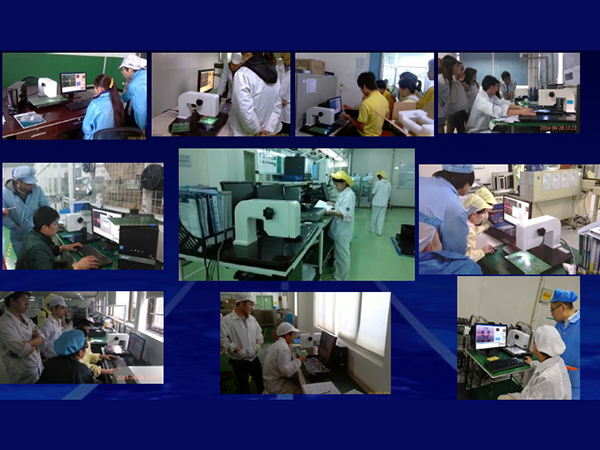
10 、Training pictures
PPT : introduction of Solder Paste Inspection
how to use Solder Paste Inspection